
Structured cabling estimating
A structured cabling estimate starts with drops and ends with certified test results. In between are cable lengths, terminations, telecom room build-out, pathways, backbone, firestopping and labeling. The project spec, usually Division 27 and often written to a manufacturer's warranty program, decides most of the details.
- Drop counts
- Average run method
- Pathways
- Testing and certification
What drives the number
- Division 27 specs: cable category (Cat 6 or Cat 6A), manufacturer system and warranty (often 20–25 years through a certified installer), jack colors, labeling standard and test requirements.
- Technology drawings (T-sheets): outlet symbols and cables per outlet, telecom room (TR) locations, rack elevations, backbone riser.
- Standards the spec cites: ANSI/TIA-568 (cabling and length limits), TIA-569 (pathways and spaces), TIA-606 (labeling), TIA-607 (bonding), and often BICSI practices.
- Who carries what: conduit and sleeves (often the electrician), firestopping, cable tray, rack power, Wi-Fi access points and active equipment.
If you're an electrical contractor carrying low voltage, check whether the manufacturer warranty requires certified installers on your crew.
The method
- Count outlets and cables by type: data, voice, wireless access point (WAP), camera, AV, building systems. Note cables per outlet (two-cable outlets are common).
- Assign each outlet to its serving TR.
- Calculate cable length per TR with the average-run method below.
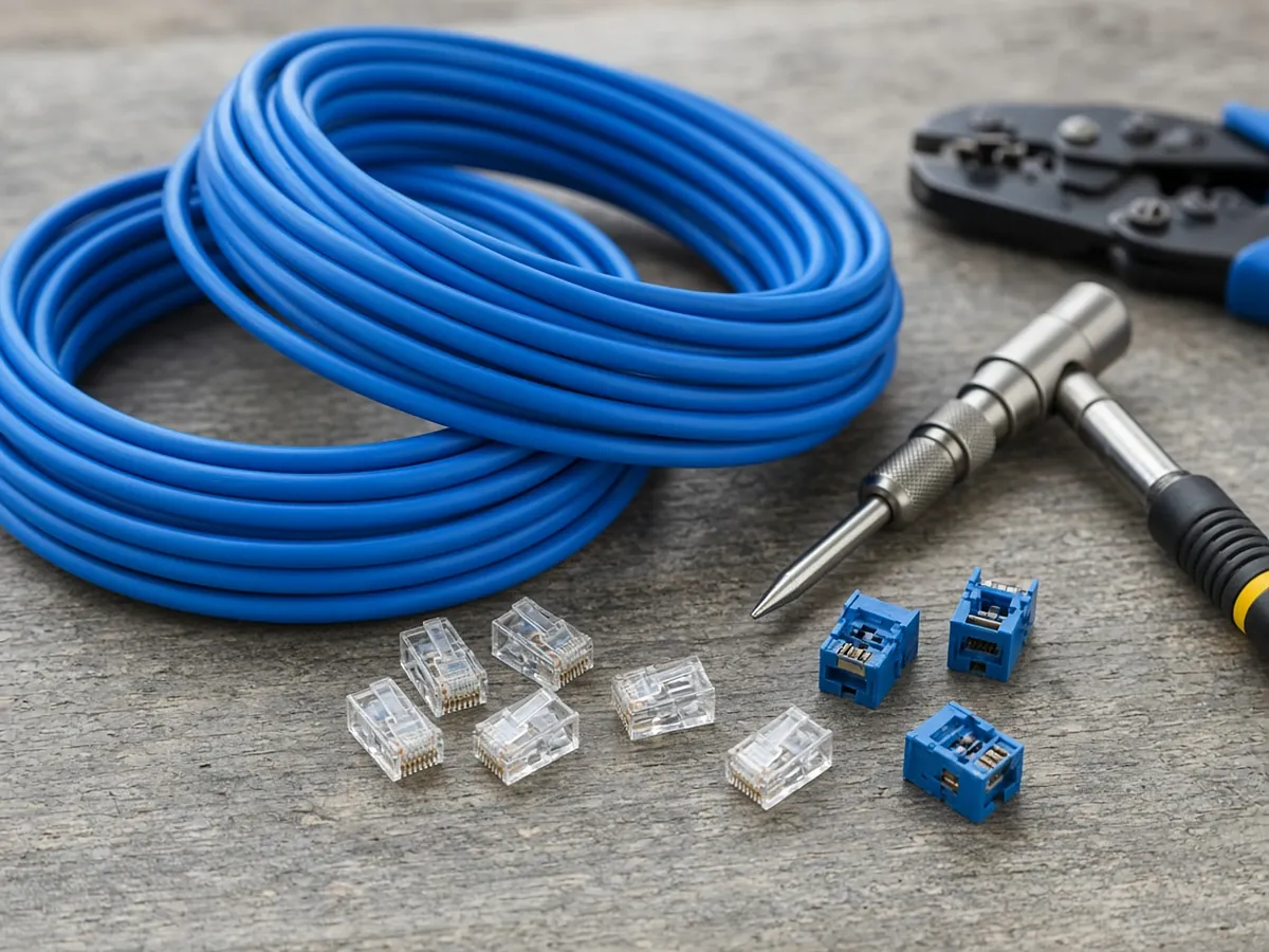
- Terminations: jacks, faceplates, patch panel ports, both ends.
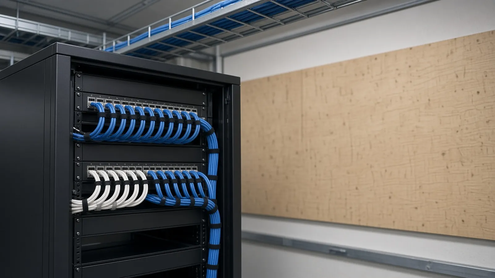
- TR build-out: racks or cabinets, cable managers, ladder rack, patch panels, grounding to the TGB.
- Pathways: J-hooks, cable tray, conduit stubs, sleeves, firestopping.
- Backbone: fiber (and sometimes copper) between TRs and the main equipment room.
- Testing, labeling and documentation: per cable and per fiber strand.
Cable length
Measure the routed path (not straight-line) from each TR to its nearest and farthest outlet, average them, then add vertical drops and slack.
Illustrative example. Use your floor plan, ceiling heights and spec slack requirements.
Nearest outlet path 40 ft
Farthest outlet path 230 ft
Average 135 ft
+ drop at outlet (ceiling to box) 10 ft
+ service loops, both ends (per spec) 10 ft
Per cable 155 ft
240 × 155 = 37,200 ft → 38 boxes of 1,000 ft (round up; add your waste factor)
Check: farthest permanent link ≈ 250 ft, under the 90 m (295 ft) TIA-568 limit
If the longest runs approach 295 ft, flag it: the design may need another TR or a relocated one. ANSI/TIA-568 limits the horizontal permanent link to 90 m and the full channel, including patch cords, to 100 m.
Rules that add cost
| Item | Common rule | Takeoff effect |
|---|---|---|
| J-hooks | Spaced no more than 5 ft (1.5 m) apart; 48 to 60 in is common in specs | Route length ÷ spacing, plus hooks at turns |
| Conduit runs (TIA-569) | No more than 100 ft between pull points and no more than two 90° bends between pull points | Pull boxes on long or bendy runs |
| Conduit fill | 40% for three or more cables | Cat 6A's larger diameter means fewer cables per conduit |
| Plenum spaces | NEC Article 800 requires plenum-rated (CMP) cable in air-handling spaces | CMP costs more than CMR |
| Rated walls and floors | Listed firestop systems at every penetration | Count penetrations; confirm who carries it |
Remodels: the NEC requires accessible abandoned communications cable to be removed. Price demolition and disposal when the spec or AHJ requires it.
Beyond the outlets
- Patch panel ports equal to cables terminated, rounded up to 24- or 48-port panels, plus spare capacity if the spec requires it.
- Horizontal and vertical cable managers per rack.
- Faceplates, jacks, blanks and labels per outlet.
- Ladder rack in the TR and above racks.
- Grounding: rack bonding conductors to the TGB per TIA-607.
- WAP and camera drops: often in the ceiling with service loops; check whether you also mount the device.
Between rooms
Take off backbone by run: route length, slack at both ends, fiber type (singlemode or multimode, OM3/OM4/OS2 per spec), strand count, connectors or splices, fiber enclosures, innerduct and riser firestopping. Fiber testing is usually Tier 1 (loss testing with a light source and power meter, OLTS) and sometimes Tier 2 (OTDR traces in addition). Tier 2 adds equipment and hours.
Pricing drivers
Most contractors price labor per drop (pull, terminate both ends, test and label) from their own history, plus separate hours for rack build-out, backbone, fiber terminations and pathway. Adjust for:
- Ceiling height and type (hard lid vs. lay-in vs. open structure)
- Occupied spaces and after-hours work
- Cat 6A (heavier, slower to terminate than Cat 6)
- Certification testing and re-terminations of failed links
- Documentation: test reports, as-builts and warranty paperwork
What to state
State cable category and manufacturer system, warranty, number of outlets and cables, test method (copper permanent link certification; fiber Tier 1 or Tier 2), labeling standard, pathway and firestopping responsibility, and exclusions such as active equipment, WAPs, rack power and conduit. That makes your number comparable with other low-voltage bids.
Drops, devices and pathways with a paper trail.
RenderDraw's AI takeoff proposes low-voltage counts and runs from the drawings, keeps the source sheet on each row, and sends uncertain items to estimator review.
- Device and drop counts. Counted against the legend and tied to the sheet.
- Pathway lengths. Proposed runs your estimator can accept or correct.
- Addenda through the same review. Send the changed sheets back through takeoff and estimator review.
- Human approval. Nothing is priced until it is accepted.
Send one low-voltage set
Files stay private while RenderDraw assesses the request. No obligation.
RenderDraw does not publish accuracy percentages or time-saved claims. Test it on your own plan set.
Questions estimators ask.
How do you estimate structured cabling?
Count outlets and cables, assign them to telecom rooms, calculate cable length, then add terminations, telecom room build-out, pathways, backbone, testing, labeling and documentation.
How do I estimate cable length per drop?
Average the routed path to the nearest and farthest outlet from each telecom room, then add the vertical drop and service loops required by the spec.
What is the maximum length for a horizontal cable run?
ANSI/TIA-568 limits the horizontal permanent link to 90 m (295 ft) and the full channel, including patch cords, to 100 m.
How far apart should J-hooks be?
No more than 5 ft (1.5 m) apart; many specs call for 48 to 60 inches. Follow the project spec.
What's the difference between Tier 1 and Tier 2 fiber testing?
Tier 1 measures loss with a light source and power meter. Tier 2 adds an OTDR trace that shows where along the fiber any loss occurs.
How many feet of cable should I allow per drop?
Use the average-run method on your own floor plan rather than a fixed number, and check every run against the 90 m limit.
Can RenderDraw count data outlets?
RenderDraw's AI takeoff proposes outlet and device counts from technology drawings with the source sheet for each, for your estimator to review. Get a free sample takeoff.
Drops counted from the plans.
Send a technology set. RenderDraw proposes outlet and device counts with sources.
- Upload the plans, specs and schedules, plus an addendum if you have one.
- RenderDraw reviews the set and the scope you want tested.
- We follow up with extracted quantities, flagged items and next steps.
Where these numbers come from
We checked this guide against the standards, manufacturer documents and industry references below (last reviewed November 2026). Figures marked as rules of thumb are typical ranges, not requirements; your project documents, local code and your own cost history govern.