How to organize the takeoff
Group the takeoff from the outside in: system first, then material and joining method, then size. The same 4 in. pipe costs very different amounts as Schedule 40 welded steel, grooved steel, Type L copper (pressed or brazed) or PVC. Any one of those is also priced differently as chilled water, steam condensate or storm drain.
| Item | Unit and basis |
|---|---|
| Pipe | LF by system, material, joining method and size, including risers and drops |
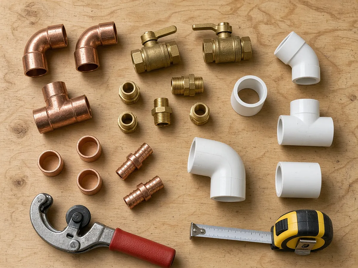
| Fittings | Each, by type and size (90s, 45s, tees, reducers, caps, flanges, couplings) |
| Valves and specialties | Each, by type, size and end connection (isolation, balancing, check, control valve install, strainers, gauges, thermometers, air vents) |
| Hangers and supports | Each, from the spacing rules plus extra at concentrated loads and direction changes |
| Insulation | LF by pipe size, thickness and jacket; fittings and valves as equivalent lengths or each |
| Sleeves, firestopping, seismic bracing | Each penetration or brace, if in scope |
| Testing, flushing, cleaning, chemical treatment | Per system, as a separate line |
Taking off from plans
- Separate systems by color or layer before you measure, and confirm the line types against the legend.
- Measure horizontal runs on plan by size. Check the scale on every sheet, and calibrate against a known dimension rather than trusting the title block.
- Add vertical pipe from sections, riser diagrams or elevation tags. Plan views do not show it, and on multistory jobs it is a large share of the footage.
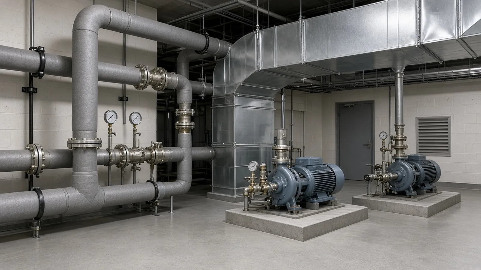
- Carry the equipment connections at each unit: valves, unions or flanges, strainer, gauges, flexible connectors and drain. These are often detailed once and apply to every unit of the same type, so multiply the detail by the tag count.
- Keep underground pipe, mechanical-room pipe and distribution pipe on separate lines. Their productivity is very different.
Taking off from isometrics
Isometrics are drawn out of scale. Use the written dimensions and elevations, never a scale ruler. Sum the segment lengths by size, get vertical lengths from elevation differences, and count a fitting at every change of direction or size.
| Segment | Size | Length | Fittings |
|---|---|---|---|
| A–B | 4 in. | 12'-6" | 90° elbow at B |
| B–C (vertical) | 4 in. | EL 110'-0" to 122'-0" = 12'-0" | 90° elbow at C |
| C–D | 3 in. | 8'-0" | 4 x 3 concentric reducer at C |
Shops differ on whether a reducer weld is counted at the larger or smaller size. Pick one convention and use it consistently.
Counting joints and diameter-inches
Piping labor is commonly estimated per joint by size, material and joining method, plus a handling allowance per foot. If the fittings are counted accurately, the joint count comes almost free:
- Elbows, reducers, couplings and inline valves each have 2 joints.
- Tees have 3 joints.
- Flanged valves have 2 flanged joints, plus the welds to the flanges.
On welded steel, many estimators total the work in diameter-inches, which is nominal size multiplied by the number of welds. A 6 in. butt weld counts as 6 DI. Productivity in hours per DI changes with schedule (wall thickness), position, material and whether the welding is done in the shop or the field. That is why carbon steel, stainless and heavy-wall pipe each need their own rates.
The joining method changes the labor more than almost anything else on the drawing. Pressed copper and grooved steel generally install faster than brazed copper or welded steel, while the fittings themselves cost more. Check the spec before you choose a method, because some owners and engineers restrict press or grooved joints on certain services.
Hangers and supports
Hanger spacing comes from the spec, which usually references MSS SP-58 (the 2025 edition superseded 2018) and the governing mechanical or plumbing code. Typical published maximum spans for water-filled standard-weight steel pipe are about 10 ft at 2 in., 14 ft at 4 in. and 17 ft at 6 in. Model plumbing-code tables cap copper tube 1-1/4 in. and smaller at 6 ft, and PVC at 4 ft. Many specs also cap all sizes at 10 ft, so the spec wins.
Also count the rod, the upper attachments (beam clamps or inserts) and the insulation shields or saddles at each hanger on insulated pipe. On seismic jobs, count bracing separately from the seismic design.
Estimating piping costs
- Material: supplier quotes for pipe, fittings, valves and specialties. Copper and steel pricing moves, so check how long each quote is good for.
- Labor: joints and footage multiplied by units, adjusted for height, congestion, occupied space and phasing. MCAA's WebLEM is the published reference most mechanical estimating software is licensed to carry. Your own job-cost history is the better basis.
- Testing: carry it as its own line. Building services piping under ASME B31.9 is normally tested hydrostatically, and the spec sets the pressure and duration (often 1.5 times working or design pressure). Testing takes labor, test equipment, water and sometimes a witness.
- Flushing and chemical treatment: hydronic systems often need flushing and water treatment before TAB. That work is usually carried as a subcontract.
Gotchas
- Material changes at a size breakpoint (copper to steel, grooved to welded) that are applied by habit instead of from the spec.
- Vertical pipe left out because the job was measured on plan only.
- Equipment connection details counted once instead of once per unit.
- Insulation carried on the wrong systems, or with no fitting allowance.
- Dielectric fittings where copper meets steel.
- Expansion loops, guides and anchors on long runs and risers.
- Make-up water, drain and vent piping in the mechanical room, which is often shown only in details.
Review checklist
- Pipe sizes agree with riser diagrams and equipment schedules.
- Every coil, pump and unit has supply and return connections with the specified valves.
- Insulation footage equals the footage of the insulated systems.
- Hanger count is consistent with footage divided by spacing, plus extras.
- Testing and flushing appear once per system.
- One length can be traced from the drawing to the priced row.
When a detailed takeoff is not the right tool
For conceptual budgets, and for small residential or tenant-improvement work, allowances per fixture, per ton or per square foot are faster and accurate enough. Use those allowances as a check against a detailed takeoff, not as a replacement for one when the drawings support counting. Process piping for industrial plants falls under ASME B31.3 and is estimated differently.
Where RenderDraw fits
RenderDraw's AI takeoff proposes pipe runs and fitting counts from drawings and links each row to its source sheet. Estimators review and accept rows before pricing. Try a free sample takeoff, or see the mechanical estimating guide and the pipe volume calculator for test-water and fill volumes.