
Column schedule takeoff example
A column schedule packs marks, sizes by tier, splice elevations and plate references into one grid. Read it carefully and it turns into column pieces, lengths and weights. Read it carelessly and you'll carry one size for the full height and miss the splices.
- Marks and tiers
- Splice elevations
- Weight per tier
- OSHA perimeter columns
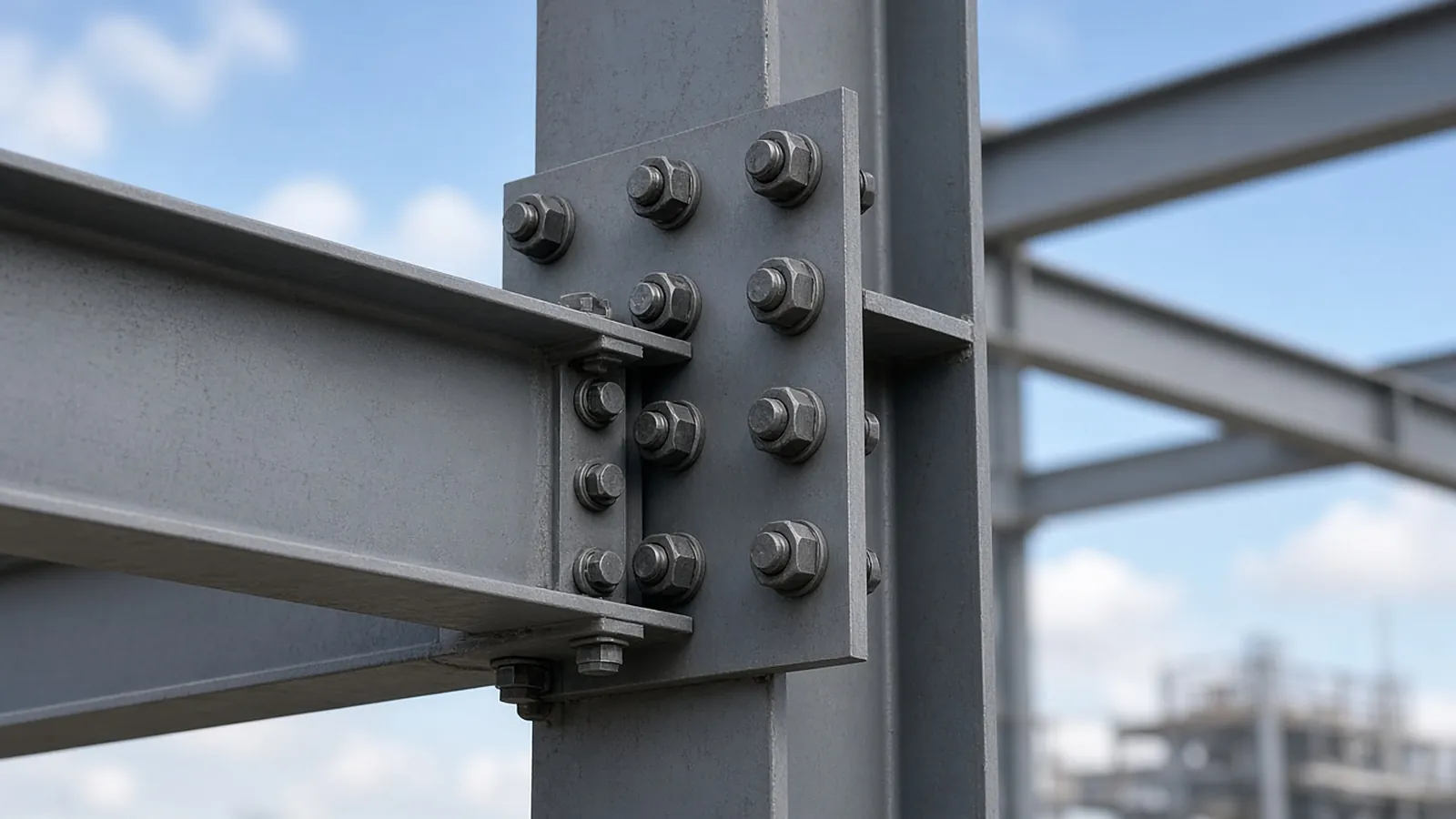
What each part tells you
- Column marks across the top (C1, C2…), with grid locations either listed or shown only on the plans.
- Levels and elevations down the side: top of footing or base plate, each floor, roof, penthouse.
- Size by tier, drawn as a vertical bar between splice levels. A W14x90 from base to the third floor and W14x61 above is two shipping pieces.
- Splice marks, usually a short horizontal line a few feet above a floor. Splices are commonly placed about 4 ft above the floor so the connection can be made from the deck. Read the dimension; don't assume it.
- Base plate and anchor rod references by type.
- Notes: cap plates, stiffeners, doublers, "orient web," and columns that start on transfer girders.
One mark, two tiers
Illustrative round numbers. Mark C3 appears at 14 grid locations.
| Tier | From – to | Length | Size | Weight |
|---|---|---|---|---|
| 1 | Base plate EL 100'-0" to splice EL 128'-0" | 28 ft | W12x65 | 28 × 65 = 1,820 lb |
| 2 | Splice EL 128'-0" to top EL 152'-0" | 24 ft | W12x40 | 24 × 40 = 960 lb |
| Per column | 2,780 lb |
Base plates (type BP-1, 14×14×1): 14 × 55.6 lb = 778 lb
Cap plates at roof (10×14×3/4): 14 × 29.8 lb = 417 lb
Splice: plates, bolts by type × 14
Pieces for erection: 14 × 2 tiers = 28 column picks
Piece length matters for more than weight. A tier over about 40 to 60 ft may hit shipping or crane limits; a long single-tier column on a high-bay building may need a splice nobody drew. Check the longest piece against your shop's handling and your trucking.
What OSHA adds to columns
Federal steel erection rules shape column detailing, so they show up in your fabrication hours:
- Perimeter columns must extend at least 48 in above the finished floor to allow perimeter safety cables before the next tier is erected, unless constructibility doesn't allow it, and must have holes or attachments for the cables at 42 to 45 in above the floor and at the midpoint (29 CFR 1926.756(e)). That is shop work: holes or cable tabs on every perimeter column.
- Column splices must be designed to resist a minimum eccentric gravity load of 300 lb located 18 in from the column face (1926.756(d)).
- Four anchor rods minimum per column (1926.755). A two-rod base on the schedule is a question.
Schedule vs. plans
Schedules list marks; plans place them. Count each mark's locations on every framing plan, then confirm:
- Every mark on the plans exists in the schedule.
- Every schedule line has at least one location on the plans.
- Columns that stop below the roof or start on a transfer girder are counted at the right levels.
- Any quantities the schedule states agree with your plan count.
A mark on the plan with no schedule entry, or a schedule line with no location, is an RFI, not a guess. Under the AISC Code of Standard Practice (§3.4), structural drawings govern over architectural ones when they conflict, and written dimensions govern over scaled ones. Note which document you priced from.
Watch for these
- Measuring to floor elevations instead of splice elevations, which shifts weight between tiers.
- One size for the full height because the tier break was missed.
- Ignoring sloped roofs and penthouses that change top-of-column elevation at certain grids.
- Missing base plate thickness, cap plate or bearing plate where the length is set to top of steel.
- Forgetting columns that appear only in sections or on the roof framing plan (screen-wall posts, dunnage).
- Skipping doubler plates and stiffeners in the notes. Under AISC 303-22 §3.2.4, reinforcement at connections that the documents don't show isn't in your bid; say so in the proposal.
What else to pick up
- Anchor rods, nuts, washers and leveling plates by base type.
- Grout under base plates (by the GC under AISC 303 §7.7 unless the contract says otherwise).
- Splice plates, bolts and field welds by splice type; full-penetration welded splices on moment-frame columns are expensive field work.
- Cap plates and beam seats at roof and transfer levels.
- Embeds and moment connections shown in details but not in the schedule.
- Keep rows by mark and tier, with the sheet reference, so a revision to one column line reprices in minutes.
What the schedule tells the erector
Splice levels set how many column pieces there are and how many times the crane comes back to each grid line. Tier count drives picks; heavy lower tiers can set crane size. Moment-frame columns with field-welded splices need welders, preheat in cold weather and inspection. Pass the piece list to whoever prices erection so both estimates start from the same count.
Member counts off the drawings, with the sheet attached.
RenderDraw's AI takeoff proposes steel member counts and lengths from plans, framing plans and schedules, links every row to its source, and sends low-confidence items to your estimator before the handoff to pricing.
- Counts and lengths by member. Proposed from the drawings and kept tied to the framing plan or schedule they came from.
- Uncertain items flagged. Items the AI can't confirm go to review instead of being guessed.
- Addenda through the same review. Send the changed sheets through takeoff and review, then reprice the members that changed.
- Your estimator decides. Connections, erection, coatings, risk and margin stay your call.
Test it on a real steel package
Send one structural set, ideally with an addendum. Sample files stay private while RenderDraw assesses the request. No obligation.
RenderDraw does not publish accuracy percentages or time-saved claims. Test it on your own plan set.
Questions estimators ask.
How do you read a steel column schedule?
Marks run across the top, levels and elevations down the side, and sizes are shown by tier between splice levels. Each tier is a separate shipping piece. Base plate types, cap plates and notes are listed per mark.
How do you calculate column weight from a schedule?
For each tier, multiply length by the shape's weight per foot from the AISC Manual, sum the tiers, then add base, cap and splice plates. Multiply by the number of locations for that mark.
Where are column splices located?
Wherever the schedule dimensions them, commonly about 4 ft above a floor so the connection can be made from the deck. Use the dimension shown.
Do perimeter columns need anything special?
Under OSHA 1926.756(e), perimeter columns must extend at least 48 in above the finished floor and have holes or attachments for perimeter safety cables at 42 to 45 in and at the midpoint, unless constructibility doesn't allow it. That adds shop work.
What if a column mark on the plan isn't in the schedule?
Send an RFI and note your assumption in the proposal. Don't assume a size.
Can RenderDraw read column schedules?
RenderDraw's AI takeoff proposes column marks and counts from framing plans and schedules with the source sheet attached; your estimator reconciles tiers and sizes before pricing. Get a free sample takeoff.
Schedules read, mismatches flagged.
RenderDraw proposes members from schedules and plans and flags where they disagree.
- Upload the plans, specs and schedules, plus an addendum if you have one.
- RenderDraw reviews the set and the scope you want tested.
- We follow up with extracted quantities, flagged items and next steps.
Where these numbers come from
We checked this guide against the standards, manufacturer documents and industry references below (last reviewed November 2026). Figures marked as rules of thumb are typical ranges, not requirements; your project documents, local code and your own cost history govern.
- 29 CFR 1926 Subpart R, Steel Erection (eCFR) — §1926.755 anchorage, §1926.756(d)–(e) splices and perimeter columns
- ANSI/AISC 303-22 Code of Standard Practice (free from AISC) — §3.2.4 member reinforcement, §3.4 discrepancies, §7.7 grouting
- AISC Steel Construction Manual, shape tables — weights per foot